What is Autosar?


 A more likely scenario is the injection of isolated AUTOSAR-“islands” in a project. This scenario gives few of AUTOSAR´s intended benefits in the short perspective but gives valuable AUTOSAR experience.
AUTOSAR (AUTomotive Open System ARchitecture) is an open and standardized automotive software architecture, jointly developed by automobile manufacturers, suppliers and tool developers. The AUTOSAR-standard enables the use of a component based software design model for the design of a vehicular system. The design model uses application software components which are linked through an abstract component, named the virtual function bus.
The application software components are the smallest pieces of application software that still have a certain functionality. The software of an application can then be composed by using different application software-components. Standardized interfaces for all the application software components necessary to build the different automotive applications are specified in the AUTOSAR-standards. By only defining the interfaces, there is still freedom in the way of obtaining the functionality.
The virtual function bus connects the different software components in the design model. This abstract component interconnects the different application software components and handles the information exchange between them. The virtual function bus is the conceptualization of all hardware and system services offered by the vehicular system. This makes it possible for the designers to focus on the application instead of the infrastructure software.
By using the virtual function bus, the application software components do not need to know with which other application software components they communicate. The software components give their output to the virtual function bus, which guides the information to the input ports of the software components that need that information. This is possible due to the standardized interfaces of the software components which specifies the input and output ports as well as the format of data exchange.
This approach makes it possible to validate the interaction of all components and interfaces before software implementation. This is also a fast way to make changes in the system design and check whether the system will still function.
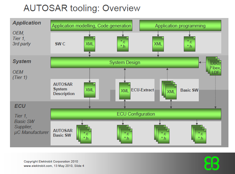
The AUTOSAR-project created a methodology that can be used to create the E/E system architecture starting from the design-model. This approach uses 4 steps:
Step 1: Input Descriptions
The input description step contains three descriptions:
- Software Components: This description is independent of the actual implementation of the software component. Among the necessary data to be specified are the interfaces and the hardware requirements.
- System: The system topology (interconnections between ECUs) need to be specified together with the available data busses, used protocols, function clustering and communication matrix and attributes (e.g. data rates, timing/latency, …).
- Hardware: The available hardware (processors, sensors, actuators, …) needs to be specified together with the signal processing methods and programming capabilities
Step 2: System Configuration
This step distributes the software component descriptions to the different ECU. This is an iterative process where ECU-resources and system-constraints are taken into account. For example, there needs to be checked whether the necessary communication-speeds are met.
Step 3: ECU-configuration
In this step, the Basic Software and the Run Time Environment of each electronic control unit (ECU) is configured. This is based on the dedication of the application software components to each ECU.
Step 4: Generation of Software Executables
Based on the configuration of the previous step, the software executables are generated. For this step, it’s necessary to specify the implementation of each software component.
This methodology is automated by using tool-chains. All subsequent methodology steps up to the generation of executables are supported by defining exchange formats (using XML) and work methods for each step.
To support the Autosar-methodology, a metamodel is developed. This is a formal description of all methodology related information, modeled in UML. This leads to the following benefits:
- The structure of the information can be clearly visualized
- The consistency of the information is guaranteed
- Using XML, a data exchange format can be generated automatically out of the meta-model and be used as input for the methodology.
- Easy maintenance of the entire vehicular system
There are four types of membership for AUTOSAR:
- Core (founding) members
- Premium members
- Associate members
- Development members
Core membership only is available for leading car manufacturers and Tier1; the other types of membership are open to other companies as well.
Core members include the PSA peugueot citroien, Toyata Motor Corporation, Volkswagen , BMW Group, Daimler AG, Ford Motor Company, Opel , and automotive suppliers Bosch, Continental AG and Siemens VDO (now Continental AG).
Benefits of Autosar:
What are the pitfalls on path to a future where the automotive industry embrace and incorporate the AUTOSAR vision?
First the industry needs to gain a common understanding on the usage of models and the different levels of abstraction. AUTOSAR are concrete design elements, while OEMs traditionally have a focus on functionality. AUTOSAR puts more responsibility on the OEM, the challenge is to transform functional requirements into AUTOSAR components and putthem together in a system.
The introduction of AUTOSAR in form of predefined design elements can lead to a cultural clash in the industry where the traditional development process is the waterfall. The development of the design elements is traditionally top-down where the elements are a result of a stepwise refining of the desired concepts in the project. The introduction of AUTOSAR is a restriction of development freedom; from the early phases in the development the resulting design must be aimed at AUTOSAR. Unresolved technical issues might impede a migration to AUTOSAR as well. Support from tools and interoperability must be resolved before a successful implementation. Even if all technical issues are resolved, the implementation of AUTOSAR on a system level is a huge leap. The development processes of vehicles E/E architectures are built on previous architectures. The scenario of an entire project starting from scratch embracing AUTOSAR is not likely.
How are vehicle functions implemented today?
• Each function has it´s own system although they may communicate through a bus
• Hardware and software are tightly connected
• Each function has it´s own microcontroller
• The number of ECU´s (Electronic Control Unit) are growning fast
• The same vendor supplies both the hardware and the software
• There are no alternative software suppliers
What will Autosar give?
• A standard platform for vehicle software
• An OS with basic functions and interface to software
• Functionality is supplied as software components
• An with basic functions and interface to software
• These components are hardware independent
• No applications of its own
• The same interface for all basic software
• The software is exchangable
• The software can be reused
• More than one supplier can compete with their software
CAN Communication:
Application Layer and RTE
Applications written in the context of AUTOSAR consist of components. These components communicate with each other via ports (component view). The communication between two components can consist of a single (AUTOSAR) signal or a whole signal group. From the view of the AUTOSAR SWC it is not known at implementation time, which communication media is used. All bus specific replications of send requests by a SWC to underlying layers and bus specific timing behavior must be done by COM or by the appropriate bus interfaces and drivers. The RTE uses the capability to send and receive signals of AUTOSAR COM. VFB's send modes corresponding to the transfer property of a signal and the transmission mode of an I-PDU.
Transmission Modes and Transmission Model Selection
COM shall provide different transmission modes for each I-PDU.
Periodic: transmissions occur indefinitely with a fixed period between them
Direct / n-times: event driven transmission with n-1 repetitions
Mixed: periodic transmission with direct/n-times transmissions in between
None: no transmission
Two of these transmission modes shall be supported for each PDU so that it will be possible to switch between both modes during runtime. To decide which of the two transmission modes is selected, COM shall provide the possibility to attach a condition to each signal within an I-PDU separately. If all conditions that are defined for signals within one specific I-PDU evaluate to true then one transmission mode shall be used for this I-PDU. If at least a single condition defined for a signal within this I-PDU evaluates not to true, then the other mode shall be used. These conditions shall be checked directly if a related signal or signal group is sent by the RTE. The attached condition on a signal for evaluating the transmission mode for an I-PDU is called transfer property. A transfer property of a signal can either be triggered or pending. A transfer property of a signal with the triggeredvalue causes an immediate transmission of the I-PDU except if transmission mode periodic or none is defined for the I-PDU. If the transfer property of a signal is pending, no transmission of an I-PDU is caused. Because of I-PDUs can contain more than one single signal there is needed a method to derive the I-PDU's transmission mode from the state of signals that are contained in one specific I-PDU. For this method signals within a signal group are treated like normal signals. For each I-PDU there is defined a Transmission Mode Selector (TMS). The TMS is calculated by evaluating the Transmission Mode Conditions (TMC) of a con gurable subset of signals belonging to the specific I-PDU. The TMS is de ned to be true if at least one TMC of the con gurable subset of signals evaluates to true. If all TMCs evaluate to false the TMS is de ned to be false. If Com SendSignal or Com SendSignalGroup are called, the TMS of the IPDU shall be re-calculated. Figure 4.2 shows the mapping of signals into an I-PDU and the evaluation of the TMS. A detailed description of the selection of transmission modes is situated in. 
In Autosar, two types of SWC communication Intra & Inter,
Client-Server Communication:
A widely used communication pattern in distributed systems is the client-server pattern, in which the server is a provider of a service and the client is a user of a service.
The client initiates the communication, requesting that the server performs a service, transferring a parameter set if necessary. The server waits for incoming communication requests from a client, performs the requested service, and dispatches a response to the client’s request. The direction of initiation is used to categorize whether an AUTOSAR Software Component is a client or a server. A single component can be both a client and a server, depending on the software realization. The client can be blocked (synchronous communication) or non-blocked (asynchronous communication), respectively, after the service request is initiated until the response of the server is received. The image gives an example how client-server communication for a composition of three software components and two connections is modeled in the VFB view.
The client initiates the communication, requesting that the server performs a service, transferring a parameter set if necessary. The server waits for incoming communication requests from a client, performs the requested service, and dispatches a response to the client’s request. The direction of initiation is used to categorize whether an AUTOSAR Software Component is a client or a server. A single component can be both a client and a server, depending on the software realization. The client can be blocked (synchronous communication) or non-blocked (asynchronous communication), respectively, after the service request is initiated until the response of the server is received. The image gives an example how client-server communication for a composition of three software components and two connections is modeled in the VFB view.
Sender-Receiver Communication:
The sender-receiver pattern gives solution to the asynchronous distribution of information, where a sender distributes information to one or several receivers. The sender is not blocked (asynchronous communication) and neither expects nor gets a response from the receivers (data or control flow), i.e. the sender just provides the information and the receivers decides autonomously when and how to use this information. It is the responsibility of the communication infrastructure to distribute the information.
The sender component does not know the identity or the number of receivers to support transferability and exchange of AUTOSAR Software Components. The image illustrates an example how sender-receiver communication is modeled in the AUTOSAR VFB view.
The sender component does not know the identity or the number of receivers to support transferability and exchange of AUTOSAR Software Components. The image illustrates an example how sender-receiver communication is modeled in the AUTOSAR VFB view.
The central structural element in AUTOSAR is the COMPONENT. A component has well-defined ports, through which it interacts with other components. A port always belongs to exactly one component. The AUTOSAR Interface concept defines the services or data that are provided on or required by a port of a component. The AUTOSAR Interface can either be a Client-Server Interface (defining a set of operations that can be invoked) or a Sender-Receiver Interface, which allows the usage of data-oriented communication mechanisms over the VFB.
A port is either a PPort or an RPort. A PPort provides an AUTOSAR Interface while an RPort requires one.
When a PPort of a component provides an interface, the component to which the port belongs provides an implementation of the operations defined in the Client-Server Interface respectively generates the data described in a data-oriented Sender-Receiver Interface.
When an RPort of a component requires an AUTOSAR Interface, the component can either invoke the operations when the interface is a Client-Server Interface or alternatively read the data elements described in the Sender-Receiver Interface.
CAN Driver: The CAN Driver is part of the lower layer and offers the CAN Interface uniform interfaces to use. It hides hardware specific properties of the CAN Controller as far as possible. The CAN Driver performs the hardware access and provides a hardware independent API to the upper layer, the CAN interface (CanIf). Services for initiating transmission are offered by the CAN Driver and it calls the callback funtions of the CanIf module for notifying events hardware independently. In addition there are services provided by the CAN Driver module to control the state of all CAN controller belonging to the same CAN hardware unit. A CAN controller serves exactly one physical channel. A detailed description of the CAN bus is given in [30]. A CAN hardware unit is represented by one CAN Driver and either on chip or an external device. It may consist of one or multiple CAN controllers of the same type and one or multiple CAN RAM areas [29]. A single CAN Driver module can handle multiple CAN controllers if they belong to the same hardware unit. If an L-PDU shall be transmitted, the CAN Driver writes the L-PDU in a buffer inside the CAN controller hardware and if an L-PDU is received, the CAN Driver module calls the RX indication callback funtion with the L-PDUs ID, the DLC (see: ch. 2.3) and with a pointer to the L-SDU. The CAN Driver can access hardware resources and converts the given information for transmission into a hardware speci c format and triggers the transmission. The CAN Driver module offers the CanIf services to control the state of the CAN. Controllers by callback functions for bus-off and wake-up events. It implements the interrupt service routines for all CAN hardware unit interrupts that are needed. While startup the CAN Driver initializes static variables including flags, sets common settings for the complete CAN hardware unit and sets CAN controller specific settings for each CAN controller.
Communication Manager (ComM): The ComM is a resource manager which encapsulates the control of the underlying communication services. It controls the basic software modules related to communication and coordinates the bus communication access requests. The ComM shall simplify the usage of the bus communication stack for the user. It shall offer an API for disabling the sending of signals, shall be able to control more than one communication bus channel of an ECU and shall simplify the resource management by allocating all resources necessary for the requested communication mode. The COM Manager (ComM) controls the starting and stopping of sending and receiving I-PDUs via AUTOSAR COM. The NM is used by the ComM to synchronize the control of communication capabilities across the network.
CAN/FlexRay/LIN Bus State Manager: The actual bus states are controlled by the corresponding Bus State Manager. The actural states of the bus corresponds to a communication mode of the ComM. The ComM requests a specific communication mode from the state manager and the state manager shall map the communication mode to a bus state.
E.g. the comM uses the API of the CanSM to request communication modes of CAN neworks. The CanSM uses the API of COM to controll CAN related PDU groups and it communicates with the CanIf to conrol the operating modes of the CAN controllers and to get noti ed by the CanIf about peripheral events.
Network Management Modules (NM) The Generic Nework Management Interface adapts the ComM to the bus specific network management modules. It provides an inteface to the ComM and uses services of the network management modules. The bus specific network management modules are CAN NM, FlexRay NM and LIN NM. The AUTOSAR NM Interface can only be applied to communication systems that support broadcast communication and bus-sleep mode. For network management data exchange the PDU Router module is bypassed.
DCM(Diagnostic Communication Manager): The main purpose of the DCM is providing a common API for diagnostic services. It is used while development, manufactoring or service by external diagnostic tools [25]. In gure 3.5 there is an overview of the communication over the DCM. The DCM performs the scheduling of diagnostic PDUs. It acts as a user by requesting full communication from the ComM if diagnostic shall be performed.
A more likely scenario is the injection of isolated AUTOSAR-“islands” in a project. This scenario gives few of AUTOSAR´s intended benefits in the short perspective but gives valuable AUTOSAR experience.
Drawbacks of AUTOSAR: The methodology used for mapping AUTOSAR concepts on existing has serious drawbacks.
•If both the existing concept and the newly introduced AUTOSAR concept carry the same information, there is a risk of inconsistency. There is also a risk of confusion over which concepts to use, but this is easily resolved by making the old concept abstract thereby forcing the use of the new concept
• Conflicting inheritance. Even if individual concepts map perfectly on each other, they can be parts of inheritance structures violating AUTOSAR. On behalf of multiplied information and the risk of inconsistency the problem can theoretically be resolved with multiple inheritances. In practise the problems cannot be resolved; SystemWeaver does not support multiple inheritances. The final part of the implementation of the prototype meta model in an existing meta model is more of a demonstration piece; the implementation is what usually is called “ugly hack” In order to implement a fully working AUTOSAR meta model the usual customisation of the SystemWeaver is necessary, not only with respect of the customers needs but also with respect to AUTOSAR´s requirements.
How they have standardised the Autosar Basic Software modules(BSW)?
In Every module, there are standardised functionality for example ADC, The main function of ADC is to convert Analog to Digital conversion. So, we can develop standard functions but the channel, Bit resolution, Interrupts might be changing based upon the microcontroller and hardware pins. In Each module, we can have configuration files for Hardware related information and Standard functions for modules main functionality. In each BSW (Basic Software module) Configuration files which are configured using tools(Eg: EBTresos, EcuSpectrum, DaVinci Configurator) we can generated configuration files and Standardized function which are defined as per autosar SWS specification.
How to generate the System Description files and ECU Description files?
Load the Dbc(Can Database) or LDF(Lin Description File) or Fibex (Field Bus Exchange) in Configuration tool and Configure the missing parameter as per System Description Template and extract the System Description arxml file using Export option. We can generate the ECU Description file using ECU extract option after loading the System Description file. After the extraction of ECU Description arxml load it configuration tool and configure the BSW modules as per autosar SWS Specification document.
- System Configuration Description:
includes all system information and the information that must be agreed between different ECUs - System Configuration Extractor:
extracts the information from the System Configuration Description needed for a specific ECU - ECU extract:
is the information from the System Configuration Description needed for a specific ECU - ECU Configuration Description:
all information that is local to a specific ECU the runnable software can be built from this information and the code of the software component
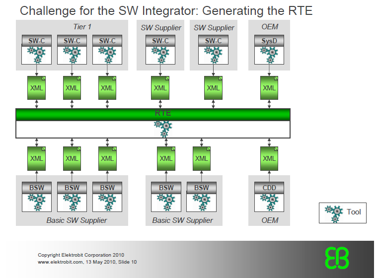
What is meant by RTE module? How to do RTE Generation using configuration tools?
In Rte Generation, there are two phases,
1. RTE Contract Phase
2. RTE Generation Phase
For Rte generation, Each Software component should have Ports(PPorts, RPorts), Interface(Client-Server/Sender-Recevier), Runnables, Rte Events should be mapped to the concern components. In generation of SchM module which will generate the task bodies, BSWMDT(BSW Module Description Template) is the input for generation of SchM, which is a part of RTE generation.
Please find the reference documents to know in brief about AUTOSAR.
- AUTOSAR_EXP_LayeredSoftwareArchitecture
- Autosar_ppt
- 27239727-Automotive-Embedded-System-Development-in-AUTOSAR
- lesson19_autosar
- CommunicationStack_gosda
FAQs in AUTOSAR:
- What is AUTOSAR?
- What is SWC?
- Difference between Intra ECU and Inter ECU Communication?
- What is meant by Client-Server Communication and Sender-Receiver Communication
- What is meant by Communication Stack?
- What is Pack and Unpacking IPdu?
- What is MDT(Minimum Delay Timer)?
- What is TMS (Transmission Mode Selection)?
- Explain about AUTOSAR COM module?
- What is RTE ? What are its function?
- How the SWC interact with CAN module?
- What is NM?
- What are functions of CANSM, CANIF & CAN module?
- Example of DET errors?
- Example of DEM errors?
- What is the functionality of DCM module?
- What is meant by MCAL Layers?
- Explain the AUTOSAR architecture?
- What are the pros & cons of AUTOSAR?
- What is meant by Pre-Compile, Post-Build & Link Time?
estes acontecimentos podem ser o estopim de algo muito maior que estava para vir. Read More
ReplyDeleteAutomotive Hub: Autosar Basics >>>>> Download Now
Delete>>>>> Download Full
Automotive Hub: Autosar Basics >>>>> Download LINK
>>>>> Download Now
Automotive Hub: Autosar Basics >>>>> Download Full
>>>>> Download LINK EN
What Imapct wrench do you advise? Looking for high torque ones like
ReplyDeletethis
HI,
ReplyDeleteI want to know the difference between ApplicationDataType and ImplmentationDataType.
These provided information was really so nice,thanks for giving that post and the more skills to develop after refer that post. Your articles really impressed for me,because of all information so nice.
ReplyDeleteAutomobile Chatbot
Automotive Chatbot
Chatbots for Automotive Industry
Car Chatbot
Car Dealer Chatbot
AI Chatbot for Car Dealers
Automotive Hub: Autosar Basics >>>>> Download Now
ReplyDelete>>>>> Download Full
Automotive Hub: Autosar Basics >>>>> Download LINK
>>>>> Download Now
Automotive Hub: Autosar Basics >>>>> Download Full
>>>>> Download LINK Sg